Chris's tip actually works for removing the oil seal and carrier from 1938/9 on half shafts (and for the similar axles for 44 years up to the end of P5B production in 1973!)
Full details in the RSR P2 Workshop manual, but this may help.
UPSET PATTERN AXLE SHAFTS
MODELS. 10 and 12 h.p. 1937-47 (Commencing Car Nos. 701950 and 711950).
14 h.p. 1937-47 (Commencing Car No. 721201).
16 h.p. 1937-47.
20 h.p. 1937-40.
Note: On 1937 models the line of demarcation between old type “built-up” and new type “upset “ shafts can always be determined by the ABSENCE of a hub retaining nut on the “upset shaft,
Axle shafts of the “upset type have been adopted on all models listed above, They are made from one forging, i.e. in such a manner that the hub and shaft are integral and their chief advantage is increased strength over shafts of the normal “built-up ‘I pattern.
It is felt that some guidance is desirable for their repair, and as slight changes in design have taken place within the models covered by this Bulletin, the assemblies may be divided into two groups for this purpose.
A shaft of different pattern from the original (as governed by these two groups) may have been fitted, so that in all cases reference should first be made to Figs. 1 and 2 to determine which type is fitted, and then proceed with the operation according to the appropriate group.
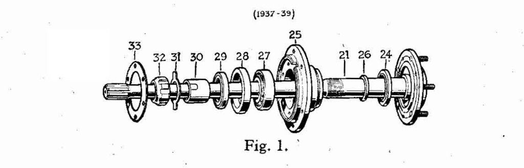
GROUP I. All Models 1937-39 (Fig. 1).
A. TO ASSEMBLE.
The axle shaft, bearing housing and brake anchor plate are assembled first, and then the complete unit is fitted to the axle casing.
Proceed as follows :—
1. Press oil seal (24) into the recess provided on the outer face of the bearing housing (25),
Note: Oil seals must always be fitted with the “knife-edge” towards the oil; in this instance that means towards the centre of the axle,
2. Press the’ taper roller bearing (27) into the bearing housing (25).
3, Fit oil seal (29) into sleeve (28), insert distance tube (30) into the bearing
housing (25) and press the oil sleeve (28) over the distance tube and into the bearing housing until it abuts the roller bearing.
4, Mount the brake anchor plate to the bearing housing and secure with six bolts, spring washers and nuts,
5, Fit distance washer (26) to the axle shaft (21) and press the axle shaft through the bearing housing, the housing being supported on the inner face of the distance tube (30),
6. Fit lock-plate (on some models only), lock-washer (31) and locknut (32).
Note: Axle shafts are fitted with a left-hand thread on the nearside and a right- hand thread on the offside,
7. Mount the complete assembly to the axle casing, adding sufficient shims (33) to permit barely perceptible end-float and secure with six bolts, spring washers and nuts.
Shims (33) are obtainable .005”, .01-2” and ,064 in thickness.
B. TO DISMANTLE.
The complete axle shaft assembly may be removed from the axlecaing after withdrawing the six bolts on the banjo flange.
Then proceed as follows :—
1. Remove lock-nut, lock-washers and distance tube (30).
2. To dismantle the bearing housing from the axle shaft, support the bearing housing face and press on the splined end of the shaft; it may be necessary to assist with a sharp blow on the shaft with a brass drift. A hydraulic or heavy-duty press, capable of a load up to 20 tons, will be required, and care should be taken to ensure that the pressure is applied squarely to the shaft.
3, Remove the inner oil-seal and sleeve by pressing out the inner roller-race ring. The outer ring will remain in position and a suitable extractor is required for its removal.
4. The outer oil-seal cannot be removed without it being damaged in the process, but as this item need only be replaced if it is defective, the point is of no consequence.
5. Remove the brake anchor plate from, the bearing housing.
best regards
Mike