Hiya,recently on a local journey i glanced across to check the fuel situation before going too far away from a filling station,and found the reading to be on 1/4 full.After a couple of miles the reading was on zero,so off to the filling station and put in £30 of fuel to find the reading still on zero.
I have removed the Float Etc from the tank,had the windings checked and was told that it was OK.I have also checked by earthing the wire that attatches to the sender but no movement at the gauge.I have checked the continuity of that same wire and that is OK.The oil reading on the gauge still operates as usual.
Could someone please give me some assistance as to what to check and how to check next,as i am clueless.I look forward to your replies. Regards Ray Horne
1937 Rover 10 Fuel Gauge Readings
-
paul williams

- Posts: 238
- Joined: Wed Sep 24, 2008 12:47 pm
- Location: Telford,Shropshire
- Contact:
Re: 1937 Rover 10 Fuel Gauge Readings
Hi Ray,
when you ground the lead at the sender you should get full scale on the gauge. If not and you are sure that the cable is good then the gauge must be faulty.Might be worth grounding directly at the gauge to double check.
There are different types of guages.
Have a look at
http://auto.howstuffworks.com/fuel-gauge2.htm
which shows how one type works works, you may be able to use a more modern substitute to test the system but I am guessing you will either have to open up the guage internals or seek professional help
Note, the rover does not use a voltage stabiliser, the gauge may have a live feed and a feed from the tank sender to compensate for voltage fluctuations (otherwise the fuel gauge would wander as the battery charged and loads like headlamps were switched on) so the internals of the gauge may not be the same.
From what I remember as well as the bimetallic type another type is a multi-coil type gauge which effectively is a balanced bridge ( aka Wheatstone Bridge ) which uses balanced currents through three coils and the sender unit, making it voltage independent I am not sure which one the Rover uses, I have some old ones in the garage but they are from P4s so may not be relevent.
I think you may have to look inside the guage to find out, if you have a multimeter it is possible to check for continuity problems.
Paul
just been digging around on the net and found
http://mgaguru.com/mgtech/electric/fg_03.htm which shows in detail how the coil type of gauge works, I was slightly wrong its not a balanced bridge in the true sense, more of an unbalance magnetic field.
Having thought about this a little more, I dont think the early Rovers use the bimetalic type I am almost certain that they use the coil/magnetic type. I will have alook at the 1950 type I have to see what happens. I hope I havent confused the issue but I think we can ignore the bimetallic type.
UNLESS SOMEONE ELSE KNOWS DIFFERENT
Paul Williams
1929 2litre Saloon
1934 P1 10HP
1951 Rover Cyclops
1974 P6 3500
1998 LR Discovery I
-
RodScarman
- Posts: 15
- Joined: Sat May 02, 2009 10:18 pm
Re: 1937 Rover 10 Fuel Gauge Readings
Hello. Ray, Paul and All.
Ray,
In your posting you say. " The oil reading on the gauge still operates as usual " If you are sure of this, its hard to see how the Gauge itself can be faulty. The two [oil & petrol] Senders are electrically similar, so how is it? One sender works but not the other.
The Gauge is both complicated and tricky to work on, so in view of the above I'd check all other things first.
As you and Paul have tried most obvious things Perhaps you could also consider:
1] The Press Switch [petrol/oil switch] has brass contacts are these clean? Do the contact "fingers" push down firmly? Also is its associated wiring OK?
2] Despite you're saying you've had the Sender checked, I'd still have another look at the "Resistance Winding" inside the unit, it operates dry [except for petrol vapour] and over the years it may become worn and dirty, so it may be worthwhile cleaning it with a cotton bud soaked in contact fluid. The "wiper" can be cleaned by inserting a slip of thin paper between it and the winding [similar to using a feeler gauge] The wiper should make contact throughout its travel. The actual value of its resistance in Ohms doesn't matter (presuming it worked in the past) As the float arm is rotated it should smoothly change in value from say, 0.5 - 100 Ohms or whatever. As with most work on these cars its much better to use an old fashioned meter and not a digital one (as with a digital meter the reading will jump about all over the place)
A few years ago I spent days trying to calibrate my petrol gauge, and even now its still not right, but I did learn a few quirky things about them [The mgaguru, link that Paul gave seems to give a detailed and logical approach although its for a later type than those used on P2's] Thanks Paul. But you [Ray Paul] Are looking for a fault and hopefully you will be able to avoid opening the gauge.
My 47/12 uses the coil type of gauge. But Im not sure about your car, is it a saloon or coupe? The Club P2 Parts List 1939/47 shows various gauges and senders [as tank sizes varies between different models] At a guess it is a coil type.
I hope you are able to solve the problem and look forward to hearing how you got on..
Rod Scarman 47/12t
.
Re: 1937 Rover 10 Fuel Gauge Readings
Hiya,thanks you Rod & Paul for your input,i must admit that i have been busy these last few days,but have had both the gauge and sender out on the bench with the help of a friend that seems to know what he is doing,and low and behold the set up works perfectly.Get it all back in the car and nothing works so my next thing totry is getting a good earth on both sender and gauge.Will keep you informed of my progress as and when i can get to it.Regards Ray
-
Castellated nut
- Posts: 17
- Joined: Thu Sep 03, 2009 9:22 pm
- Location: Shropshire
Re: 1937 Rover 10 Fuel Gauge Readings
Did you have the oil/petrol change-over switch in circuit when you tested the system on the bench, Ray? As Rod suggested above, this seems to me a very likely cause of the problem.
Re: 1937 Rover 10 Fuel Gauge Readings
This was covered in a recent Freewheel, Piet Bergveld's article is appended, see diagram on http://i973.photobucket.com/albums/ae21 ... lmeter.jpg
"The Jaeger Petrol and Oil meter. Internal and external connections. By Piet Bergveld, Enschede,NL
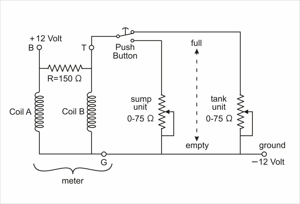
For about 10 years I have been busy with the total restoration of my Rover 16 (1938). One of my problems was to repair the petrol & oil gauge, as the internal wires were partly disconnected. Because I could not find a replacement gauge, I had to find out how the operational mechanism of this type of meter was originally meant to be. The gauge contains internally two coils and one resistor, thus six wires, which should be interconnected in such away that via three external connections it could operate in conjunction with the tank unit and oil unit, respectively. Evenings of internet search did not lead to an answer, but fortunately, based on some information Mike Maher sent me, I was able to reinvent this principle of monitoring liquid levels, or in fact electrical currents.
In the schematic drawing, coil A is meant to electromagnetically attract a revolving piece of soft iron to which the pointer is connected. If the coil carries an appropriate current, this attraction brings the pointer to the full position. Note that, because I changed the polarity of the battery, terminal B of the meter is connected to + 12 Volt, after the ignition is switched on. Whereas in the usual analogue current meters the movement of the pointer is counteracted (balanced) by a spiral spring, in the case of the Jaeger meter the counteraction is provided by a second coil, coil B, which is connected to the T terminal of the meter. This counteraction is variable, because the +12 Volt at terminal B is divided between the internal resistor of 150Ω (ohms) and the variable tank or oil unit resistor (depending on the pushbutton position). When the fuel tank or sump is full and the float is in the upper position, these resistors are 0Ω (ohms)(i.e. short circuited) and thus coil B is not carrying any current. This means that the pointer reads full, due to the current through coil A.
For an empty tank or sump, (float in the lower position), the variable resistors are approximately 75Ω (ohms), thus coil B also carries a current which is in this case enough to fully counteract the (electromagnetic) action of coil A, and thus the pointer reads empty. Of course any other position of the float, and thus the resulting resistance value of the tank or oil unit, will result in a certain intermediate position of the pointer, corresponding to the present liquid level in the tank or sump.
Note that it is essential that an earth (ground) lead (G) is connected to the – 12 Volt terminal (common), which is actually the mounting bolt of the case of the meter. Whereas usual current and volt meters have only 2 leads to be connected, the system as used by Jaeger, needs 3 leads.
The beauty of this arrangement is that gauges can be calibrated, so if the readings “full” and “empty” are not at the proper point of the scale, the coils can to be shifted in slots in the mounting case. In my case I had to move coil B slightly in the direction of the revolving soft iron, whereas coil A had to be moved in the other direction. This may however differ from meter to meter."
"The Jaeger Petrol and Oil meter. Internal and external connections. By Piet Bergveld, Enschede,NL
For about 10 years I have been busy with the total restoration of my Rover 16 (1938). One of my problems was to repair the petrol & oil gauge, as the internal wires were partly disconnected. Because I could not find a replacement gauge, I had to find out how the operational mechanism of this type of meter was originally meant to be. The gauge contains internally two coils and one resistor, thus six wires, which should be interconnected in such away that via three external connections it could operate in conjunction with the tank unit and oil unit, respectively. Evenings of internet search did not lead to an answer, but fortunately, based on some information Mike Maher sent me, I was able to reinvent this principle of monitoring liquid levels, or in fact electrical currents.
In the schematic drawing, coil A is meant to electromagnetically attract a revolving piece of soft iron to which the pointer is connected. If the coil carries an appropriate current, this attraction brings the pointer to the full position. Note that, because I changed the polarity of the battery, terminal B of the meter is connected to + 12 Volt, after the ignition is switched on. Whereas in the usual analogue current meters the movement of the pointer is counteracted (balanced) by a spiral spring, in the case of the Jaeger meter the counteraction is provided by a second coil, coil B, which is connected to the T terminal of the meter. This counteraction is variable, because the +12 Volt at terminal B is divided between the internal resistor of 150Ω (ohms) and the variable tank or oil unit resistor (depending on the pushbutton position). When the fuel tank or sump is full and the float is in the upper position, these resistors are 0Ω (ohms)(i.e. short circuited) and thus coil B is not carrying any current. This means that the pointer reads full, due to the current through coil A.
For an empty tank or sump, (float in the lower position), the variable resistors are approximately 75Ω (ohms), thus coil B also carries a current which is in this case enough to fully counteract the (electromagnetic) action of coil A, and thus the pointer reads empty. Of course any other position of the float, and thus the resulting resistance value of the tank or oil unit, will result in a certain intermediate position of the pointer, corresponding to the present liquid level in the tank or sump.
Note that it is essential that an earth (ground) lead (G) is connected to the – 12 Volt terminal (common), which is actually the mounting bolt of the case of the meter. Whereas usual current and volt meters have only 2 leads to be connected, the system as used by Jaeger, needs 3 leads.
The beauty of this arrangement is that gauges can be calibrated, so if the readings “full” and “empty” are not at the proper point of the scale, the coils can to be shifted in slots in the mounting case. In my case I had to move coil B slightly in the direction of the revolving soft iron, whereas coil A had to be moved in the other direction. This may however differ from meter to meter."
Re: 1937 Rover 10 Fuel Gauge Readings
Hiya all,thanks to all your inputs,with my problem.I think i have cracked it,there are 3 wires at the rear of the gauge,one on its own and two connected together.The single wire is connected to the OIL press button,the connection was loose,i have tightened it up and all seems to work perfectly,just to be on the safe side i have earthed both sender and gauge.
Thank you all very much for your help.
Keep to the Left ,Regards Ray
Thank you all very much for your help.
Keep to the Left ,Regards Ray