This was covered in a recent Freewheel, Piet Bergveld's article is appended, see diagram on
http://i973.photobucket.com/albums/ae21 ... lmeter.jpg
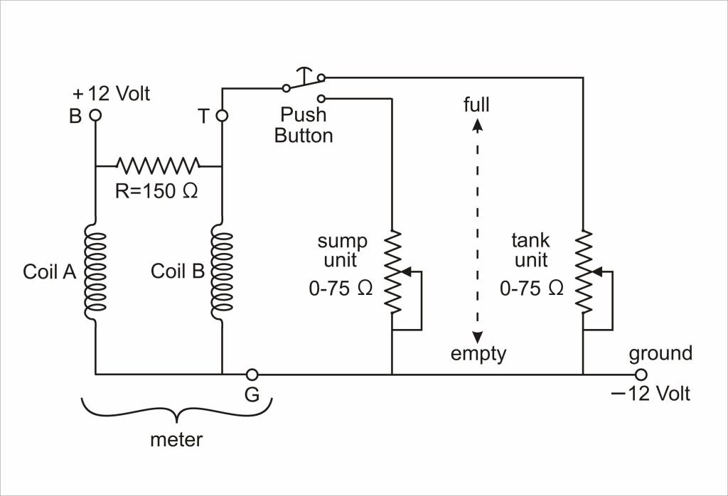
"The Jaeger Petrol and Oil meter. Internal and external connections. By Piet Bergveld, Enschede,NL
For about 10 years I have been busy with the total restoration of my Rover 16 (1938). One of my problems was to repair the petrol & oil gauge, as the internal wires were partly disconnected. Because I could not find a replacement gauge, I had to find out how the operational mechanism of this type of meter was originally meant to be. The gauge contains internally two coils and one resistor, thus six wires, which should be interconnected in such away that via three external connections it could operate in conjunction with the tank unit and oil unit, respectively. Evenings of internet search did not lead to an answer, but fortunately, based on some information Mike Maher sent me, I was able to reinvent this principle of monitoring liquid levels, or in fact electrical currents.
In the schematic drawing, coil A is meant to electromagnetically attract a revolving piece of soft iron to which the pointer is connected. If the coil carries an appropriate current, this attraction brings the pointer to the full position. Note that, because I changed the polarity of the battery, terminal B of the meter is connected to + 12 Volt, after the ignition is switched on. Whereas in the usual analogue current meters the movement of the pointer is counteracted (balanced) by a spiral spring, in the case of the Jaeger meter the counteraction is provided by a second coil, coil B, which is connected to the T terminal of the meter. This counteraction is variable, because the +12 Volt at terminal B is divided between the internal resistor of 150Ω (ohms) and the variable tank or oil unit resistor (depending on the pushbutton position). When the fuel tank or sump is full and the float is in the upper position, these resistors are 0Ω (ohms)(i.e. short circuited) and thus coil B is not carrying any current. This means that the pointer reads full, due to the current through coil A.
For an empty tank or sump, (float in the lower position), the variable resistors are approximately 75Ω (ohms), thus coil B also carries a current which is in this case enough to fully counteract the (electromagnetic) action of coil A, and thus the pointer reads empty. Of course any other position of the float, and thus the resulting resistance value of the tank or oil unit, will result in a certain intermediate position of the pointer, corresponding to the present liquid level in the tank or sump.
Note that it is essential that an earth (ground) lead (G) is connected to the – 12 Volt terminal (common), which is actually the mounting bolt of the case of the meter. Whereas usual current and volt meters have only 2 leads to be connected, the system as used by Jaeger, needs 3 leads.
The beauty of this arrangement is that gauges can be calibrated, so if the readings “full” and “empty” are not at the proper point of the scale, the coils can to be shifted in slots in the mounting case. In my case I had to move coil B slightly in the direction of the revolving soft iron, whereas coil A had to be moved in the other direction. This may however differ from meter to meter."